
About This File
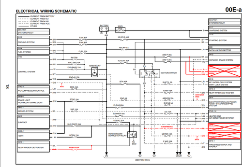
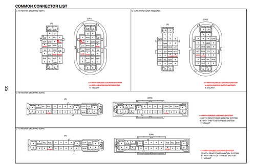
MAZDA 5 ELECTRICAL WIRING SCHEMATIC
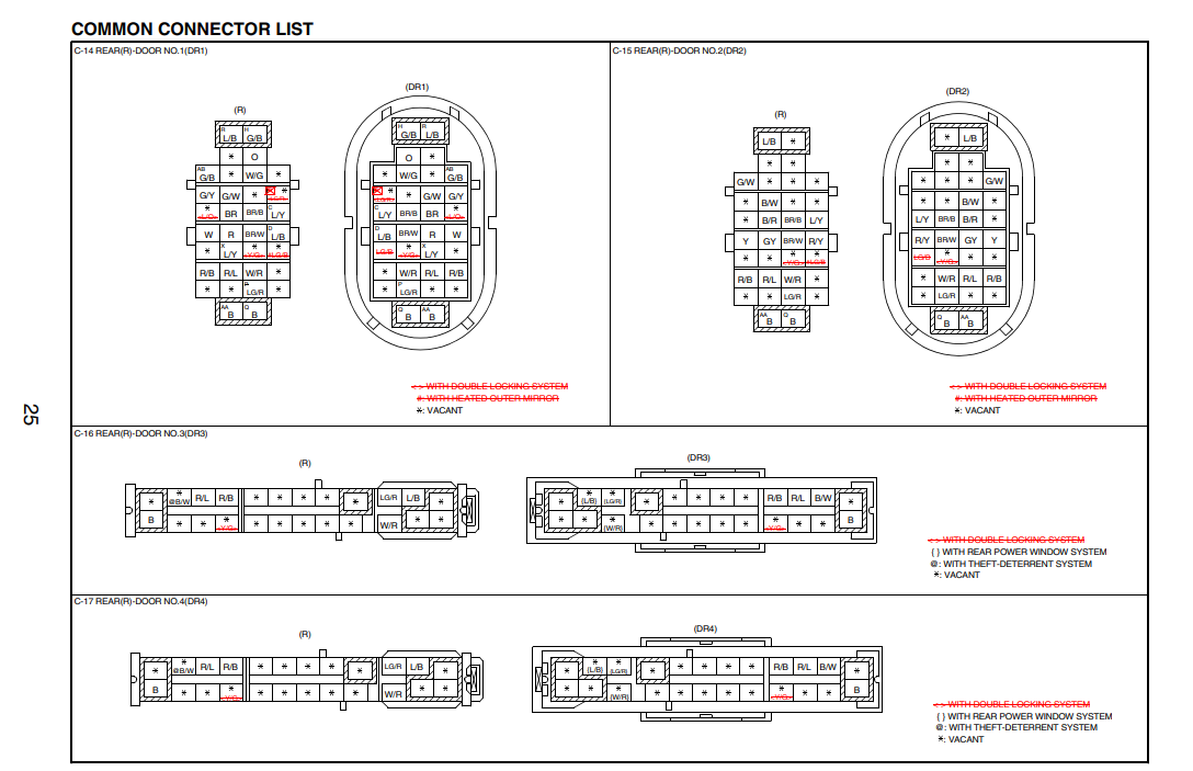
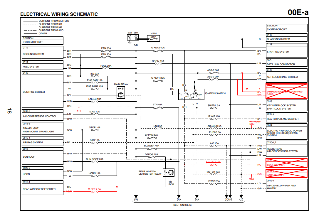
Mazda 5 electrical wiring schematics vary significantly across its two main production generations and engine configurations.
Platform Generations & Architecture
-
First Generation (CR Series, ~2005–2010):
-
Architecture: Ford C1 platform derivative (shared with Mazda 3 BK, Ford Focus Mk2).
-
Bus Systems: High-Speed CAN (HS-CAN: PCM, ABS/DSC, TCM, EPS) and Mid-Speed CAN (MS-CAN: Instrument Cluster, PJB).
-
Central Power/Body Control: Controlled by the Passenger Junction Box (PJB) located behind the glove compartment, which houses body fuses, solid-state switches, and internal relays.
-
-
Second Generation (CW Series, ~2011–2018):
-
Architecture: Updated Ford/Mazda C1 platform (shared with Mazda 3 BL).
-
Bus Systems: Upgraded HS-CAN and MS-CAN topologies; modified PJB/BCM routing and redesigned motorized power sliding door controllers.
-
Standard System Schematics Overview
-
Power Distribution & Starting/Charging:
-
Battery & Main Fuse Block: Engine compartment fuse box (Main Relay, Starter Relay, Alternator B+ circuit).
-
PJB / Cabin Fuse Box: Distributes switched IG1, ACC, and constant +12V feeds across cabin electronics.
-
-
Powertrain & Engine Management (PCM):
-
Pinouts cover crank/cam position sensors (CKP/CMP), coil-on-plug packs, injector drivers, throttle body (drive-by-wire), and oxygen/air-fuel ratio sensors (LF/L3 2.0L/2.3L/2.5L MZR petrol or MZ-CD diesel).
-
-
Power Sliding Doors (PSD Modules):
-
Dedicated left/right PSD controllers, touch latch switches, encoder motors, open/close limit sensors, and hazard warning buzzer circuits.
-
-
ABS / DSC / EPAS:
-
Active wheel speed sensors (hall effect), steering angle sensor, yaw/lateral G-sensor, and electric-hydraulic/electric power steering rack connectors.
-
Standard Wire Color Codes (Mazda / Ford)
| Code | Color | Typical Function |
| B | Black | Ground (GND) |
| W | White | Switched / Signal line |
| R | Red | Constant Battery (+12V B+) or Power |
| BR | Brown | Sensor Reference / Signal Ground |
| Y | Yellow | Ignition Switched (IG/ACC) / Logic |
| G | Green | Indicator / Switch / CAN-L (pair-dependent) |
| L | Blue | Control / CAN-H (pair-dependent) |
| O / V / P | Orange / Violet / Pink | Dedicated Module Signals & Bus Lines |
Two-color wires use the primary body color followed by the tracer stripe (e.g., B/W = Black with White stripe).
Common Ground Points
-
Point 01 / 02: Front inner fender wells (battery ground, PCM, lighting).
-
Point 07 / 08: Base of A-pillar / kick panels (PJB ground, cluster, cabin electronics).
-
Point 12 / 14: C/D-pillars and rear floor panel (fuel pump, tail lamps, sliding door drives).
To pull the exact pinout or wiring path, which model year, engine size (e.g., 2.0L LF, 2.3L L3, 2.5L L5), and specific circuit (e.g., PCM pinout, power sliding doors, starter/PJB)
HOW TO DOWNLOAD 















.thumb.png.3b9e9f8c1f76904aafa83323e53319ce.png)
![More information about "PERKINS SPI2 [2023.05]"](https://lymuna.org/uploads/monthly_2026_07/20282828ge3.thumb.png.844bb6c4916a1fbeb3fdfd443dbf9ffd.png)
























![More information about "HPT Tune Repository 3500 FILES [1997/2018]"](https://lymuna.org/uploads/monthly_2023_05/Capture.thumb.PNG.4952bb41d4a0f784c43b4abb4a4b4136.PNG)









.thumb.png.402c8fdc183028cda5dcc29671fbafdb.png)








.thumb.jpg.3fd3239c5d782486ba5613400c7acd0f.jpg)
.thumb.jpg.89a455ba1fe01f5d589c8319fe63320b.jpg)